Getting Started
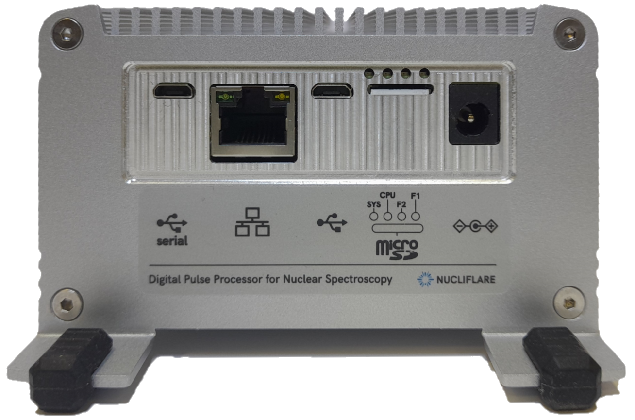
Front panel
Symbol |
Description |
|---|---|
|
DC 12 V Power Barrel Connector Jack 2.10mm ID (0.083”), 5.50mm OD (0.217”). Power consumption is max. 15W. |
|
microSD card connector. Firmware and software storage device. |
|
LEDs. From the left: Sys, CPU, F2, F1. The state of F2 LED corresponds to the LOGIC IN input state. The state of F1 LED corresponds to analog signal coverage on any channel. |
|
miniUSB 2.0 compatible with USB gadget mode. Connecting the digitizer via this connector to a computer will create a new network interface on this computer and set up a local network on it. DPP static IP is 192.168.3.1 |
|
1GbE RJ45 Ethernet socket. The Ethernet cable should be connected before powering on the device for proper network initialization over DHCP. |
|
miniUSB 2.0 Linux terminal (115200 8N1) based on the CP2102N. Download USB to UART Bridge VCP Drivers: https://www.silabs.com/developers/usb-to-uart-bridge-vcp-drivers |


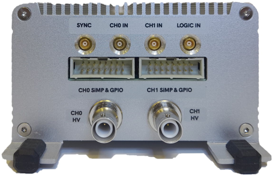
Back panel
Output |
Description |
|---|---|
SYNC |
MCX, 3.3V CMOS logic external trigger input for synchronization. |
CH0 IN |
MCX, Channel 0 analog input. |
CH1 IN |
MCX, Channel 1 analog input. |
LOGIC IN |
MCX, 3.3V CMOS logic input. |
CH0 HV |
SHV, Channel 0 photomultiplier power supply output. |
CH1 HV |
SHV, Channel 1 photomultiplier power supply output. |
CHO SiPM & GPIO |
IDC16, Channel 0 SiPM power supply and GPIO connector. |
CH1 SiPM & GPIO |
IDC16, Channel 0 SiPM power supply and GPIO connector. |
Warning
Do not disconnect HV cables and SiPM power supply cable during operation!
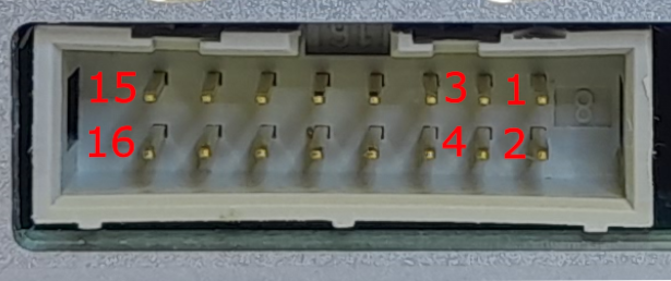
SiPM & GPIO connector pinout
Pin |
Description |
|---|---|
1 |
SiPM power supply output. |
3 |
+5 V power supply output. |
5 |
-5 V power supply output. |
7 |
analog temperature sensor input. |
9 |
analog temperature sensor power supply output. |
10 |
12 V power supply output. |
11 |
GPIO power supply output. |
13 |
GPIO0 |
14 |
GPIO1 |
15 |
GPIO2 |
16 |
GPIO3 |
2 |
Ground pin. |
4 |
Ground pin. |
6 |
Ground pin. |
8 |
Ground pin. |
12 |
Ground pin. |
DPP communication interfaces
Nucliflare digitizer is a stand-alone device based on the Linux operating system. Communication with the system is mainly based on the client/server model and network communication.
Note
Debug interface
Connect DPP to the PC using  , check the serial port number, and open any serial terminal software.
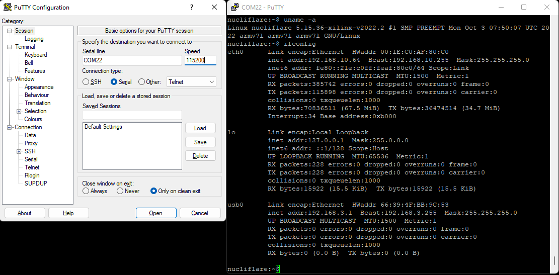
USB 2.0 Gadget interface
Connect DPP to the PC using  , local network between DPP and PC will be established. Run Nucliflare DPP software. DPP static IP is 192.168.3.1
Ethernet connection
Connect DPP to local network using  connector. Check IP address using Debug interface or USB 2.0 Gadget interface and ssh connection.
Note
The IP address of a device on a local network usually remains constant for the next power cycles.
Running digitizer & quick start
